ELECTROLEVEL standard sensors have the following dynamic parameters:-
VialType | Natural frequency | damping factor @ 25°C |
A | 1.0 Hz | 0.6 |
C | 2.5 Hz | 0.9 |
In common with all viscous damping mechanisms these values of damping factor increase at lower temperature and decrease at higher temperature.
Natural frequency however is insensitive to temperature.
It is possible to modify the above standard damping factors to suit particular applications.
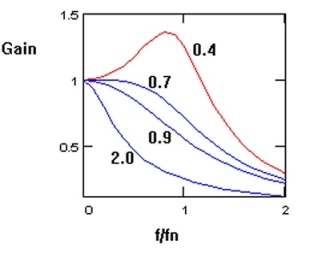
These two parameters, natural frequency and damping factor can be used in standard formulae to evaluate the ELECTROLEVEL response in a given application (Figure 1).
In many cases the great flexibility of electronic circuitry can be used to tailor the dynamic response to suit the application.
In certain applications, for example when measuring the Heel angle of a ship, the steady-state angle is being measured and the oscillating component (caused in this case by the Roll motion of the ship due to wave action) is not required. .
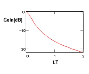
To reduce this oscillating component a time constant circuit can be fitted to the electronic detector. A simple time constant circuit with characteristic time constant T attenuates signals with frequency above 2 /T at a rate of 6dB per octave (Figure 2).
When specifying the value of T for a given application, the settling time for a new steady reading to stabilise must be taken into account. Following a sudden step change in the steady reading, the new reading will reach 90% of its final value after 2.3T and 99% of its final value in 4.6T.
The final choice of T is thus a trade-off between settling time for the desired reading and the attenuation of the oscillating signals. Values of T in the range 2 - 60 seconds are typical.
More complex circuits can be incorporated in the electronic detector, which provide sharper cut-off at high frequencies with the optimum settling time, or to enable a variety of time constants to be switched into circuit.
Note that because the ELECTROLEVEL is a pendulous device, when it is mounted on a moving structure, it will respond to horizontal accelerations of the structure in the plane of rotation of the sensor. A separate application note
The ELECTROLEVEL as an accelerometer
describes this in more detail.
|